Analog Filter Design & Simulation
Overview
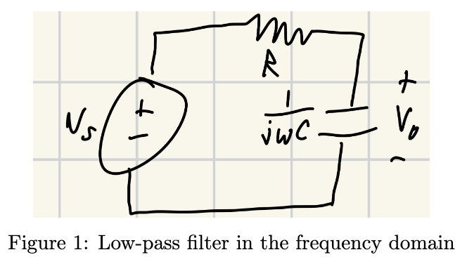
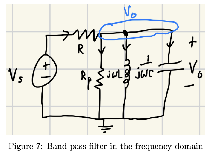
Designed and analyzed three frequency-selective circuits: an RC low-pass filter, RL high-pass filter, and RLC band-pass filter.
Approach
- Derived transfer functions, magnitude and phase responses, and cutoff-frequency equations.
- Selected resistor, capacitor, and inductor values, then modeled each design with LTspice AC-sweep simulations.
Outcome
The RC low-pass cutoff was 79.58 kHz; LTspice simulated 79.51 kHz—a 0.08% difference. The remaining filters matched within 0.07% and 0.01%.